Introduction
The fixed memory system of the Block II Apollo Guidance Computer consists of 6 physical core rope memory modules holding a total of 36,864 16-bit words. Each module contains 512 cores, which hold 192 bits of information apiece, for a total of 98,304 bits, or 6,144 words. This information is physically woven into the rope module during manufacturing. For any given core, there are 192 sense wires, each of which is either threaded through the core (indicating a 1) or bypasses the core (indicating a 0).
Like regular core memory, the cores in a core rope exhibit magnetic hysteresis — i.e., they can be magnetized either clockwise or counter-clockwise, and retain this state indefinitely once external magnetic forces are removed. In regular core memory this magnetization stores one bit of information; in rope memory, it is effectively used for addressing.
The cores in rope memory are much larger than their core memory counterparts. They have an outer diameter of about 0.25". Instead of being solid ferrites, they are made with 0.000125"-thick mo-perm (molybdenum permalloy) tape wound around a steel bobbin. This slightly softer magnetic material reduces the magnetic force required to flip the larger core's polarity. Furthermore, the extreme thinness of the tape reduces eddy currents inside the core, allowing the switching to happen faster.
There are two main components of addressing core rope memory: core selection and strand selection.
Core Selection
Magnetic Properties and Basic Wiring
The goal of core selection is to select a single core out of the 512 in a module. This is done in two phases: the "set" phase and the "reset" phase. During the set phase, current is run through a set of wires that cause only the core being addressed to flip its magnetization. During the reset phase, strand select circuits are activated to allow reading of data, and the core is switched back to its original state.
To change the polarity of a core from its default "reset" state to its "set" state, a strong current — 450mA in the AGC — is run through the core's Set wire. This pushes the core's magnetic flux to the other side of the B axis, to its saturation point. When the set current is stopped, the core settles into a new, reversed, magnetic state. The core can be returned to its original state by running 450mA in the opposite direction through its Reset wire.
For a single core, just these two wires are sufficient. If the Set and Reset wires thread through more than one core, then additional wires are needed to prevent all of the other cores from switching. These are the Inhibit wires, which are also threaded through the cores to carry current opposite the direction of the Set current. Inhibit wires are woven in pairs, with each pair separating the cores into two zones in different ways. Each Inhibit wire carries 225mA when active. The magnetizing force acting on the core depends only on the net sum of current running through it; so if two Inhibit wires are active when the Set wire is activated, the net current will be (-225mA) + (-225mA) + (450mA) = 0, and the core will not switch.
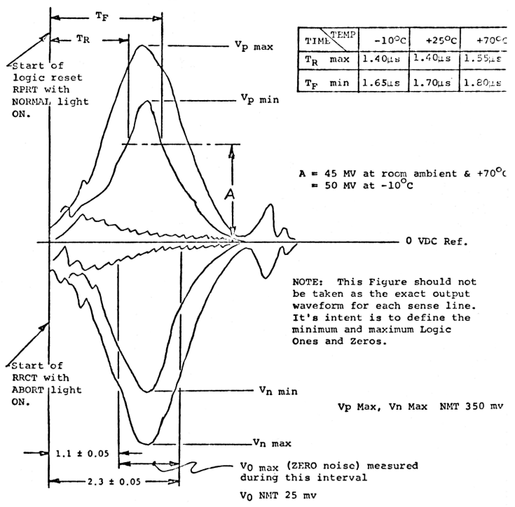
According to Faraday's law of induction, a change in magnetic flux will induce a voltage on wires passing through that magnetic field. This is the means by which 1s and 0s are stored in rope. When a core is switched, all sense wires passing through it will have an approximately 100mV pulse induced on them (indicating a 1); any wires that do not pass through the core will not (indicating a 0). Up to 25mV of noise on the sense wire is acceptable for a 0.
AGC Rope Organization
The 512 cores in a rope memory module are arranged in two physical 8×32-core layers. The diodes and resistors that form the strand selection networks line these layers on three sides, wired together in a cordwood structure.
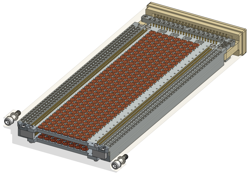
Despite the physical arrangement, the cores are logically grouped into four "planes" — A, B, C, and D. Each layer is divided lengthwise into two 4×32 planes.
All address-related wires are activated or deactivated based directly off of the least significant 9 bits of the FMA (Fixed Memory Address) of the location being read:
| Bit | Name | Function |
|---|---|---|
| 1 | IL01 | Activates IL01 during set time if 1, or IL01/ if 0. |
| 2 | IL02 | Activates IL02 during set time if 1, or IL02/ if 0. |
| 3 | IL03 | Activates IL03 during set time if 1, or IL03/ if 0. |
| 4 | IL04 | Activates IL04 during set time if 1, or IL04/ if 0. |
| 5 | IL05 | Activates IL05 during set time if 1, or IL05/ if 0. |
| 6 | IL06 | Activates IL06 during set time if 1, or IL06/ if 0. |
| 7 | IL07 | Activates IL07 during set time if 1, or IL07/ if 0. |
| 8 | RESET | Selects between RESETA (0) and RESETB (1) if bit 9 is 0, or between RESETC (0) and RESETD (1) if bit 9 is 1. |
| 9 | SET | Activates SETAB during set time if 0, or SETCD if 1. |
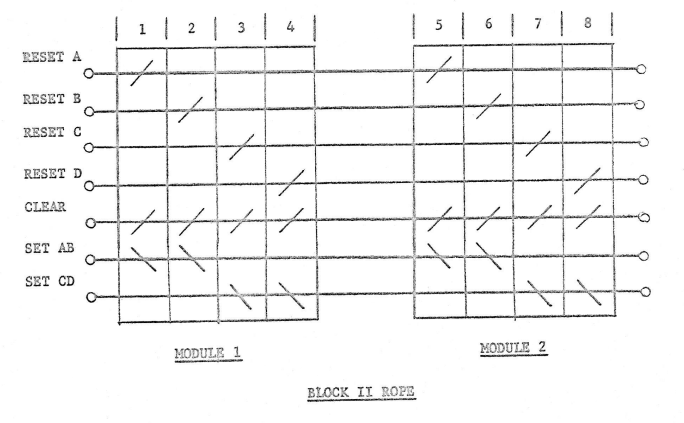
One Set wire threads through every core in both planes of a physical layer. SETAB threads all of the A and B plane cores, and SETCD threads through the C and D plane cores. Each plane has its own dedicated Reset wire — RESETA, RESETB, RESETC, and RESETD.
Inhibit wiring is accomplished via inhibit wires IL01 through IL07 and IL01/ through IL07/. Each IL0x and IL0x/ split all 512 cores in the module into two 256-core groups in different ways. Seven inhibit wires is not enough to uniquely select 1 out of 512 cores. When one wire from each of the seven inhibit pairs is activated, the remaining uninhibited cores number 512 / 27 = 4.
The Parity Inhibit Wire
One additional pair of inhibit wires were added: the parity inhibit wires ILP and ILP/. These wires are woven based on the parity (number of 1s) in the least significant 8 bits of the address. ILP is activated if the number of 1s is even, and ILP/ if it is odd. This guarantees that the parity inhibit wire will be active in every core whose address differs by only 1 bit. The parity inhibit current was increased to 300mA (vs 225mA for normal inhibits) because of the one core in the same physical layer that receives only the parity wire as inhibition.
The Design Flaw and the Fix
A design flaw wasn't caught until relatively late in the Block II logic design. When an address differs from the target in both bit 8 and one other bit (1-7), no inhibit wires — including parity — will be active in that core. Seven such cores exist for any given address, all in the opposite plane of the same physical layer.
The MIT/IL engineers found an elegant solution: also activate the 450mA Reset wire corresponding to the opposite plane during the Set cycle. This strongly inhibits all cores in that plane.
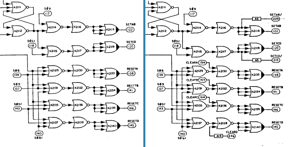
With all of this — 7 inhibit wires, 1 parity wire, 1 reset wire, and 1 set wire — one single core in the module is switched during the Set phase. The Reset phase is simpler: only the Reset wire for the switched core's plane needs to be activated, and as the core switches back, voltage is induced on all sense wires threading through it.
The CLEAR wire is threaded through every core. Pulsing 350mA through it guarantees that whatever core got set is reset — used when a rope cycle needs to be aborted after the Set phase but before Reset.
Strand and Module Selection
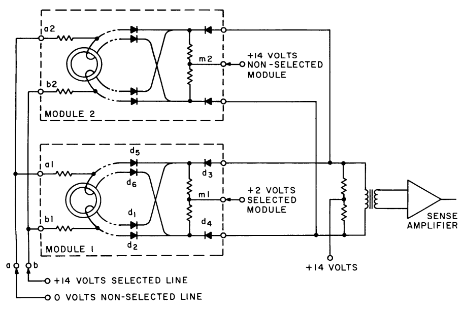
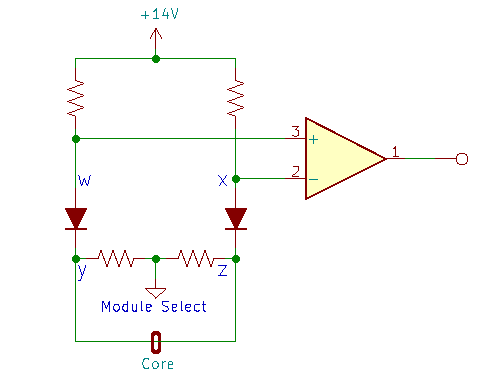
The strand selection circuitry selects 16 sense wires (one word) out of the 192 available from the switched core. Additionally, since core selection wires are connected in series between paired modules, the Set cycle sets two cores — one in each module of a pair. Module selection uses resistor-diode networks to pass signals from only the desired module.
References
- Digital Development Memo #219: Core Rope Memory Selection, Block II
- Digital Development Memo #239: Block II Rope Memory Circuits and Timing
- Apollo Block II and LEM Computer Design Review
- JDC 04255: Fixed Memory Test
- R-500: Space Navigation Guidance and Control, Volume II
- ND-1021042: LEM Primary Guidance, Navigation, and Control System Manual, Volume II